Battery Internal Resistance & Short Circuit Current.
Battery internal resistance and short circuit current values are available from battery manufacturers. The method used to arrive at the published values varies but when a method recognised by International Standards is used a comparison between products can be considered.
Searching the internet will reveal many papers discussing actual case studies where a battery has been shorted and interesting results have been obtained. With no fuse or battery circuit breaker in the system short circuits may result in fires and catastrophic failure. Alternatively, the protection may work and isolate the battery from the point of failure and the load resulting in loss of power to the equipment which the battery was intended to protect. It therefore follows that the subject of battery short circuit current can have at least two points of view when looked at in practical terms.
The internal resistance may be used to calculate the theoretical short circuit current but the method used is open to debate. Never the less, values of the internal resistance may be used to estimate the actual short circuit current in a battery system.
This article discusses how the battery manufacturer arrives at the published internal resistance and short circuit currents. It also looks at how the short circuit current may be estimated in a practical system.
ACTUAL SHORT CIRCUIT TESTS.
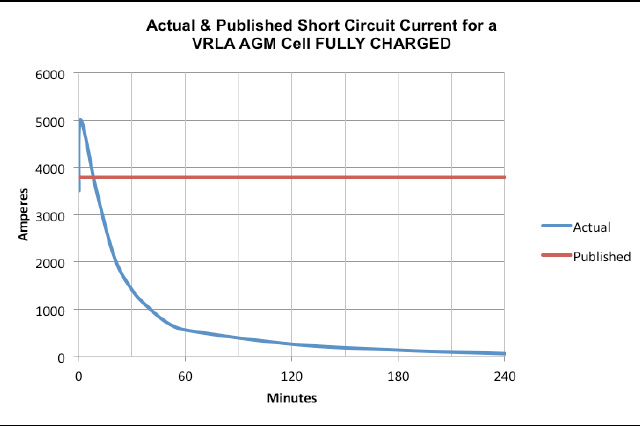
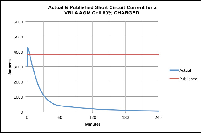
Some manufacturers carry out actual short circuit tests to determine the characteristics. The test method normally involves fully charging the product which has been “characterised” to establish the real performance compared with the actual performance. It is not unusual for the real performance to be considerably better than that published. For this reason, the manufacturer will state that the values obtained are from actual testes on a typical product taken from production. However, there is more to this than simply carrying out the test. The value of the “short” in terms of resistance must be considered. Clearly it is not acceptable to simply connect two connectors coming from the cell pillars and running the test. In one extreme the connectors may melt and act like a fuse, and in the other extreme, the connectors may be large solid copper bars which cannot be easily attached to the cell terminals. Typically, the manufacturer will look at an accepted Standard which will give some guidance to the method that should be used.
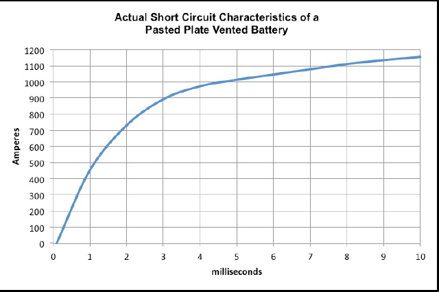
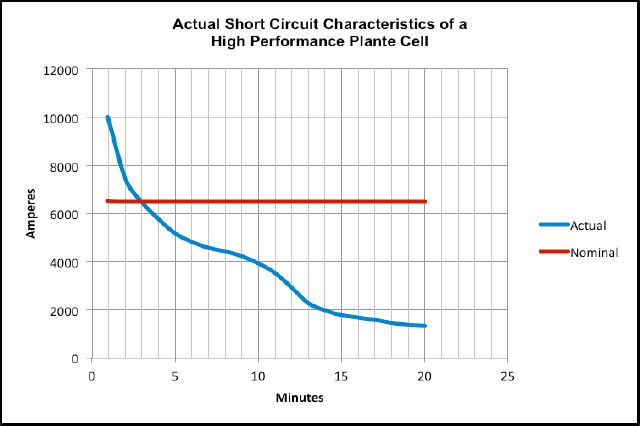
The results of actual short circuit testing are very interesting. Within the first few microseconds no current flow is seen. After a few milliseconds the current starts to flow and will rapidly increase to a peak before falling back and eventually reducing to a value somewhere close to the nominal published value. The current will continue to fall and in some cases, may flow for several hours before reaching zero.
THEORETICAL SHORT CIRCUIT VALUES.
Actual short circuit testing is interesting but they do not necessarily give repeatable value that can be used for comparison purposes. Circuit resistance, temperature and actual state of charge all contribute to variable results. The point where the current should be measure has the largest variation. Measurements taken after 1 second will show a large variation when compared with those taken after 1 minute. With this in mind, tests have shown that a “projected” result formulated from actual tests give the most repeatable results. Because the tests are based on the same datum points, comparisons to other products can be made with good accuracy.
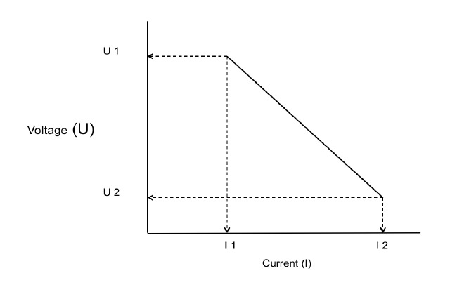
The methods which is used by most manufacturers involves discharging at two different rates and plotting the U/I characteristics. Typically, one discharge will be at a moderately high current and after a pre-determined discharge time the actual voltage and actual current will be recorded. The pre-determined discharge time will be quite short to minimize the Ah capacity removed but will be sufficiently long for reasonably stable results to be obtained. The discharge will be terminated and the product will be stood on open circuit and allowed to recover for a few minutes before a second discharge is carried out. This second discharge will be at a higher current of typically three times the value of the first current. Again, after a pre-determined time the actual voltage and actual current will be recorded and the test completed.
The internal resistance is then calculated as follows: -

The short circuit current is then calculated by ohms law where 2.00V may be used in the calculation. Some manufacturers may use the typical open circuit voltage of the cell which will largely be dependent upon the specific gravity of the cell. Values between 2.05V and 2.15V may be used.

HOW DO WE USE THE VALUES OBTAINED?
The value of internal resistance may be used to estimate the short circuit current in a practical circuit.
Example 1
Consider a 250 Ah cell having a published internal resistance of 0.33mΩ.
The battery has a total of 24 cells connected in series giving a total cell resistance of 0.33 x 24 = 7.92mΩ. The external circuit has an estimated resistance of 0.5 mΩ.
The estimated short circuit current is: -
I = (24 x 2.00V) / ((24 x 0.33mΩ) + (0.5mΩ) = 48V / 8.42mΩ = 5,701A
In comparison, the published short circuit current for a single cell is 6,150A.
Example 2
Consider a 2500 Ah cell having a published internal resistance of 0.049mΩ.
This battery has 240 cells and the external circuit has a resistance if 21mΩ.
The short circuit current is estimated to be:-
(240 x 2.00V) / ((240 x 0.049mΩ) + 21mΩ)) = 480V / (11.76mΩ + 21mΩ) = 480V / 32.76mΩ = 14,652A.
TYPICAL INTERNAL RESISTANCE AND SHORT CIRCUIT VALUES.
The internal resistance and short circuit values depend on the type of battery under consideration but as a guide, the following are typical values and are given as comparisons only. Manufacturers publish these values and the user should consult these for the correct value.
NOTE:
The values below are for guidance only and consider a 100Ah single cell. Values for multi-cell monoblocs will be different.
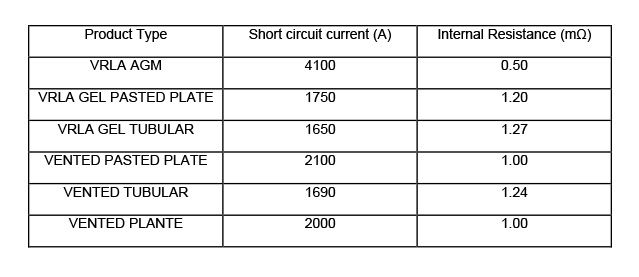
From the above table it can be seen that the VRLA AGM product has a much higher short circuit current and lower internal resistance. This characteristic is the result of thinner plates with smaller plate pitch and very low resistance separators coupled with a higher specific gravity electrolyte which enhances the open circuit voltage and initial discharge current.
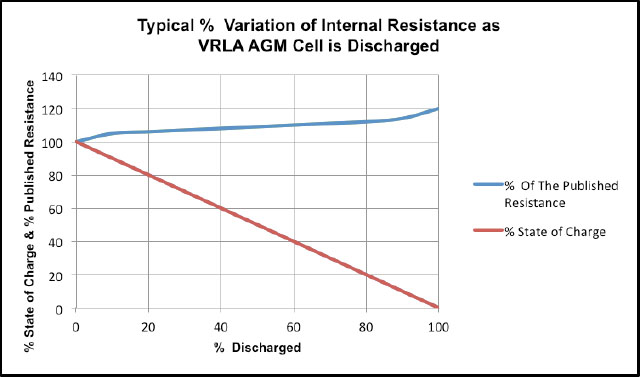
It is noted that the internal resistance of cells does not substantially vary with state of charge until the cell is more than about 80% discharged.
CONCLUSIONS.
The short circuit current of industrial standby batteries may be extremely high, even when the nominal characteristics do not suggest this.
In a real live situation, even with small batteries, it is not unusual for currents to be several thousand amperes. For large batteries such as those used in Power Stations, short circuit currents may exceed 40k amperes.
Even when the battery is not fully charged, the short circuit current is very similar to the published value because the internal resistance does not vary substantially until the cell approaches fully discharged.
ILLUSTRATIONS
Typical Method of Determination of Internal Resistance

Latest Headlines
Bulk Orders
Discounted prices are available for bulk orders, please contact us to discuss your requirement.